
The article describes a procedure which allows magnetic measurements of not completely saturated magnets with respect to the measuring conditions in an open magnetic circuit. In order to measure the magnetic properties of a new generation of Nd-Fe-B permanent magnets with high coercivity a pulsed field magnetometer is used. The measurement of the hysteresis curve of not fully saturated permanent magnets is performed by a special technique which consists of an additional measurement and a recalculation of the data. This technique allows observing the actual hysteresis curves for all states of not saturated magnetization. Furthermore the analysis exhibits that the results of measuring the magnetic properties of high coercive magnets in an ‘open-loop’ have to be discussed separately. Both cases for a not saturated permanent magnet, partially demagnetized and not fully magnetized, are examined.
Index Terms— High performance magnets, high-coercive, hysteresis, not-saturated, magnetic properties, magnetization curve, pulsed field magnetometer
I.Introduction
SEVERAL DEVICES are in use to characterize the magnetic hysteresis loop of permanent magnet material; however when it comes to the characterization of samples with volumes of more than 100 mm3, then the classical hysteresis-graph using an electromagnet with pole shoes has been used for decades. The device is normalized by the International Electro-technical Committee under [1]. However, one of the drawbacks of the device is that the pole shoes put severe constraints on the use of the device, limiting it to low coercive material and to flat extruded surfaces. With the advent of high-coercive permanent magnets, the classical hysteresis-graph shows its limitations of applying a magnetic field high enough to demagnetize the permanent magnet.
In order to overcome the limitations, pulsed field magnetometers were developed [2]-[4]. By eliminating completely the pole shoes for the field generation, the pulsed field magnetometer overcomes two major constraints: the limitations in field strength due to the saturation of the pole shoes and the requirement of the flat surface. The large fields required to fully measure the complete hysteresis of the new generation of advanced permanent magnets are conveniently provided by pulsed field solenoid magnets driven by a capacitive discharge.
Due to the elimination of the pole shoes, the pulsed field magnetometers are called ‘open-loop’ measurement systems in contrast to the classical ones which are referred to as ‘closed loop’ because the pole shoes and yoke make a closed magnetic circuit with the sample.
II.The Design of the Measurement Device
A pulsed field magnetometer used for this investigation was developed by Metis Instruments under the product name HyMPulse. The measurement system consists of a pulsed field magnet, which has a diameter of 70 mm and is water-cooled, driven by a 28 kJ – 3 kV capacitor bank. The system delivers a half-sine shaped pulsed field with a peak of 7 Tesla and duration of 20 ms (see figure 1a).
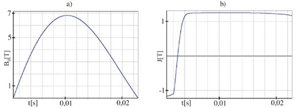
Fig. 1. a) The applied magnetic induction B0 as a function of time t showing a typical field pulse with amplitude 7 T and a duration of the half-sine pulse around 20 ms. b) The magnetic polarization J of the sample as a function of time
A pick-up coil system similar to the Helmholtz coil is used to determine the magnetic flux density B of the sample by measuring the induced voltage from the change of the magnetic flux. The process of the induction B is calculated by:
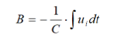
where C and ui are the coil constants and the induced voltage in the pick-up coil.
The polarization J is determined out of the magnetic induction B using the magnetic constant µ0 and the field strength H by:

In contrast to the conventional Helmholtz coil, the sensor is equipped with a series of additional winding loops. The homogeneous volume in the sensor is increased by these additional loops and the background field is compensated by a concentrical coil in series [4], [5]. The variation in the externally applied magnetic field from the pulsed field magnet Hex generates a voltage in a pick-up loop located in the bore of the field coil, but far away from the sample. The applied magnetic field is different from the field inside the sample due to the self-demagnetizing contribution from the sample itself. The field due to the self-demagnetization is proportional to the sample magnetization and a geometrical demagnetization factor N lying between 0 and 1. With this contribution, the magnetic field H inside the sample can be expressed as
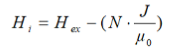
Fig. 2 shows the J(H)-demagnetization-curve of a fully saturated magnet (black) and its working point (1). When no applied field is present, the sample‘s working point is determined by the line of the self-demagnetizing field
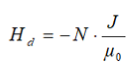
referred to as the load line [6]. The starting position for the measurement is thus located on the load line, shown in the next paragraph, in contrast to a classical system with ‘closed loop’ where it is located on the H=0 axis.
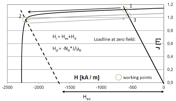
Fig. 2. Partially demagnetizing a fully-saturated high-coercive permanent magnet by using an external pulsed field (1700 kA/m field strength). The figure shows the demagnetization curves as a function of field strength H and polarization J
The hysteresis loop is measured during a single half-sine shaped field pulse, where the sample’s magnetization direction is originally positioned opposite to the magnetic field and where the magnetization is fully reversed during the pulse (see figure 1b). The spring back in polarization at the end of the measurement is because of the self-demagnetization mentioned above, that is typical for rare earth magnets. The second half of the loop is obtained via mirroring the measured half.
The signals of the inductive sensors are fed into a data acquisition system which takes care of the numerical integration. As the system is designed to accurately capture the signals over the period of the field pulse, any long term signals are not accounted for.
Proper nulling of the device is automatically done by forcing the mirror symmetry of the signal before and after the pulse: due to the symmetry of a full scale hysteresis the measured curve must be symmetric, too. Therefore, an additional measurement of the initial polarization is not necessary and the beginning of the curve can be found by forcing the mirror symmetry for the polarization at loadline.
Additionally a reference background and an eddy current measurement are made (before and after the measurement respectively) and subtracted from the hysteresis measurement. The background measurement for reference is made without any sample in the machine. The effect of eddy currents is measured by a pulsed field in the same direction as the magnetization of a fully saturated magnet.
III.Generating the Hysteresis Curve for Not-Saturated Magnets
A hysteresis curve measured by a pulsed field magnetometer normally exhibits a symmetric shape which is commonly obtained by forcing automatically the mirror symmetry on the measured data. However when the magnet is not fully saturated, i.e. when it was partially demagnetized by an external magnetic field, an unsymmetrical hysteresis curve should be observed. Therefore an additional measurement and a recalculation of the obtained J(H)-curve are necessary.
The curves obtained in this paper are hysteresis loops of the magnetic polarization J. As shown in Fig. 2, Hi is the sum of the applied external field Hex and the self-demagnetizing field Hd of the magnet. Hd without an external field is represented by the zero field loadline. After applying an external field big enough to partially demagnetize the magnet (2), it returns to a new working point (3) on the zero field loadline below the working point of the fully magnetized state [6].
If we now measure the hysteresis curve with the conventional pulsed field magnetometer we will not get the curve of the weakened magnet which is shown in Fig. 2 (grey). Due to the basic assumption made by the measurement system, the result will be a balanced curve, apparently with the same polarization for the negative and positive site of the hysteresis. For not saturated magnets this is not correct, because the measurement starts at a lower polarization Jdr’ as the polarization of the fully saturated magnet Jr’. So the curve is not symmetric. Fig. 3(a) shows schematically the left half of the curve measured by the conventional pulsed method, one for the saturated magnet (black), another for the partially demagnetized one (gray) with false symmetric polarization Jrd’.
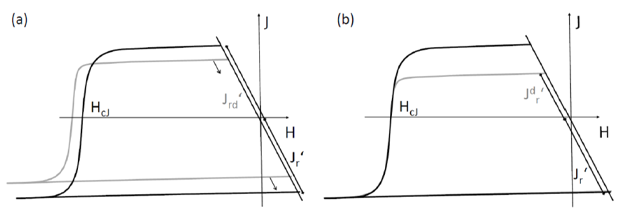
Fig. 3. a) Schematic hysteresis curves of the saturated (black) and a partially demagnetized (gray) state of a permanent magnet after forcing mirror symmetry
b) real curve after recalculation (grey) note from LVB: the load line should be identical before and aftr the shift
In case of the not saturated magnet the value of the coercivity and the position of the curve itself need additional correction. The measurement has to be recalculated in order to get the real curve. This can be done because the last part of the measurement should reflect the saturated magnet and so it ends at the same point as it would when measuring a fully saturated magnet. As demonstrated by arrows in Fig. 3(a) the curve has to be moved along the load line until the negative remanent polarizations have the same value.
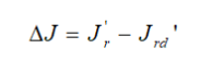
So after the first measurement of the not saturated curve the polarization of the fully saturated magnet Jr’ has to be measured. This can be done by using the pulsed field magnetometer. The difference between the polarizations of the saturated magnet Jr’ and the symmetric one of the demagnetized Jrd’ has to be subtracted from the measured curve of the demagnetized magnet.
The difference in field strength is calculated with the slope of the load line. The demagnetization factor N is known from the geometry. The factor for the cuboid shaped magnets used in this work is 0.63. So the slope s of the load line is
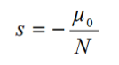
The difference in field strength H can now be easily calculated by the following equation:
After shifting both differences in polarization and field strength, the real curve of the demagnetized specimen is generated that is shown in Fig. 3(b).
IV.Verification and Discussion
A fully saturated magnet has a symmetric hysteresis curve so that measuring the half curve contains enough information to generate a full hysteresis curve. For a not saturated magnet this fact doesn’t have to be true. The real curve between load line and zero field is difficult to be measured in the ‘open-loop’, so we have to take a closer look when it comes to the extrapolation of the full curve. Sintered Nd-Fe-B magnets are used for this analysis. There are two cases that should be analyzed.
A.Partially Demagnetized
The first case is a partially demagnetized specimen, like the one used in the chapter before, explaining how the hysteresis curve for a not saturated magnet is generated. After saturating the samples with maximum field they were partially demagnetized by a pulsed magnetic field in the opposite direction with defined field strength. In this case we know that, once demagnetized, the remanent polarization will not return to its previous state without magnetizing the magnet with a positive field. The part of the curve from where the partial demagnetization ended until zero field has a constant slope
the permeability of the magnetic material. Fig. 4 shows the second quadrant plot of the hysteresis curve of a fully saturated typical Nd-Fe-B magnet with a coercivity of 2300 kA/m as reference (black) and three demagnetization states after 1700 kA/m, 1900 kA/m and 2100 kA/m field strength (grey).
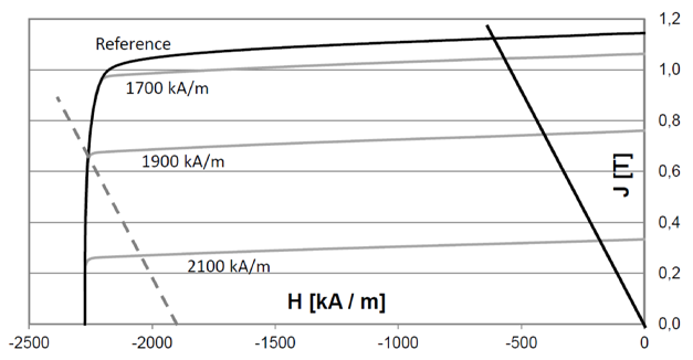
Fig. 4. Result of measuring the hysteresis curves of partially demagnetized states of a typical Nd-Fe-B specimen
As shown in Fig. 4 there is no change in direction of the curve around the load line. So the measurement can be expanded behind the load line until zero field with the slope of the permeability. Another important result shown in the picture is that after the recalculation every measurement of a partially demagnetized state of the same specimen has, as expected, the same coercivity. As mentioned above and shown in Fig. 3(a) without shifting the curve the measurement of the partially demagnetized specimen would have a greater coercivity.
The method is valid for all high coercive magnets that do not have any inconstancy in the hysteresis curve around the working point. Otherwise the results have to be treated like in the next case.
B.Not Saturated
The second case is a not fully magnetized specimen. This means it was initially not fully saturated with maximum field strength. Measurements with traditional hysteresis graphs [7] show, that the hysteresis curves of these nucleation type magnets at such a magnetized state have a precipitous beginning. Also the coercivity of each state does not have the same value. Fig. 5 shows the second quadrant plot of the hysteresis curves of the same typical Nd-Fe-B grade, one fully saturated as reference (black) and three states of different magnetization after 1000 kA/m, 1200 kA/m and 1400 kA/m magnetization field strength (grey).
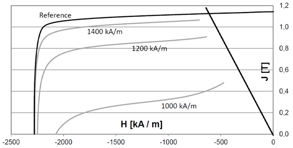
Fig. 5. Result of measuring the hysteresis curves of not saturated states of a typical Nd-Fe-B specimen
The actual slope of such a hysteresis curve measured by a classical hysteresis graph [7] and the slope that we would get from the extrapolation mentioned for partially demagnetized states are nearly perpendicular. Because of the fact that we cannot measure the beginning of the curve, which is to the right of the load line, this part of the curve has to be excluded from the results of the measurement. So the beginning cannot be substituted by the ending of the curve.
V.Conclusion
A special measuring technique for not saturated permanent magnets was developed by using a pulsed field magnetometer. It was shown, that an additional measurement and a recalculation of the J(H)-curve are necessary, because the ordinary measurement is forcing mirror symmetry for the curve, generating a false representation. With this technique we get the real hysteresis curve for all states of not saturated magnetization. The method was tested on sintered Nd-Fe-B magnets.
The analysis shows that the common assumption of symmetry in a hysteresis curve obtained by the pulsed field magnetometer needs to be cautioned. Only for saturated magnets the mirror symmetry can be assumed at the load line and therefore the beginning of the measurement can be substituted by the ending. For not saturated magnets there are two cases:
The partially demagnetized curves can be extrapolated behind the load line until zero field using the permeability of the material. This method works for permanent magnets that have continuity around the loadline.
When measuring not fully magnetized states or magnets with a discontinuous hysteresis curve around the working point the beginning of the curve cannot be extrapolated like doing so in the other case. This part has to be excluded from the result.